

 français
 русский
 español
 العربية
Search
What Are You Looking For?
Search

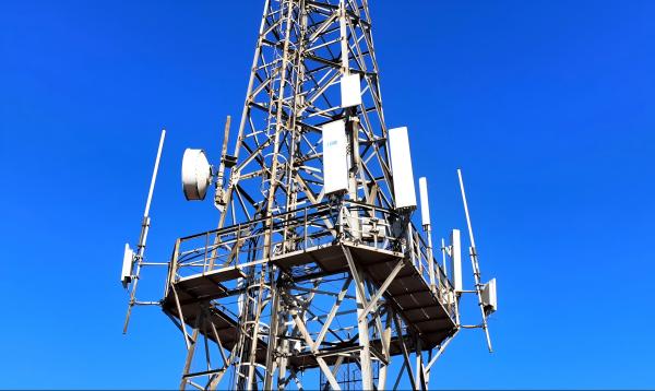
To determine the loading capacity of an Angle Steel Tower antenna pole, a comprehensive structural analysis considering various factors is essential. Here's a structured approach:
Steel Grade: Identify the steel grade (e.g., ASTM A36, A572) to determine yield strength (Fy), ultimate tensile strength (Fu), and modulus of elasticity (E).
Corrosion Considerations: Account for environmental factors that may reduce material thickness over time.
Member Dimensions: Cross-sectional area (A), moment of inertia (I), radius of gyration (r), and slenderness ratio (
KL/r) for each angle member.
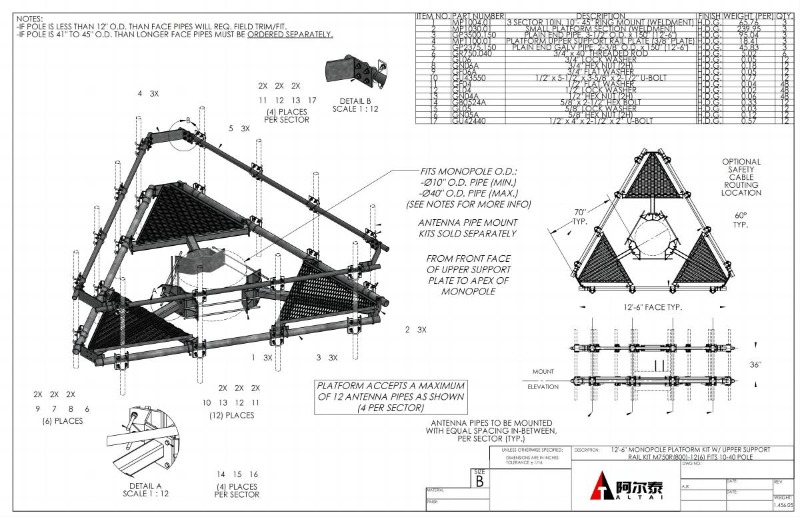
Tower Configuration: Height, base width, bracing pattern, and leg spacing influence stability and load distribution.
Dead Load: Weight of the tower, antennas, and permanent fixtures.
Live Load: Temporary loads (e.g., maintenance equipment).
Environmental Loads:
Wind Load: Calculated using wind speed (e.g., ASCE 7 or TIA-222), exposure category, drag coefficient (Cd), and projected area.
Ice Load: Adds weight and increases wind surface area; relevant in cold climates.
Seismic Load: Considered in earthquake-prone regions using seismic coefficients.
Dynamic Loads: Vibrations from antennas or wind-induced oscillations.
Axial Capacity: For compression members, check buckling using Euler's formula (
Pcr=π2EI(KL)2) and yielding (Py=FyA ).Combined Stresses: Use interaction equations (e.g., AISC) for members under axial load and bending moments.
Connections: Verify bolt/weld capacities for shear, tension, and bearing.
Relevant Standards: TIA-222 (telecom structures), ASCE 7 (environmental loads), AISC (steel design).
Load Combinations: Apply code-specified combinations (e.g., 1.2D + 1.6W).
Safety Factors: Incorporate factors of safety (e.g., 1.67 for AISC LRFD) to ensure reliability.
Wind Load Example:
Fw=0.00256⋅Kz⋅Kzt⋅Kd⋅V2⋅Cd⋅AWhere V is wind speed (mph), Kz is exposure coefficient, Cd is drag coefficient, and A is projected area.
Member Check: For a 50x50x5 mm angle (A=480 mm2, r=9.8 mm), if KL/r=100, critical stress Fcr is calculated per AISC.
Use structural analysis software (e.g., STAAD.Pro, SAP2000) for complex geometries.
Consult a licensed engineer for code compliance and final validation.
Foundation Design: Ensure the base can resist overturning moments and shear forces.
Dynamic Effects: Address potential resonance from wind or equipment.
Maintenance: Regular inspections to detect corrosion or damage.
The loading capacity is a function of material strength, geometric efficiency, applied loads, and adherence to design codes. A detailed analysis balancing these factors ensures the tower's safety and functionality. Always involve a structural engineer for critical application.
Learn more at www.alttower.com


 IPv6 network supported